Address
304 North Cardinal
St. Dorchester Center, MA 02124
Work Hours
Monday to Friday: 7AM - 7PM
Weekend: 10AM - 5PM
Address
304 North Cardinal
St. Dorchester Center, MA 02124
Work Hours
Monday to Friday: 7AM - 7PM
Weekend: 10AM - 5PM
之前有教過拍照然後送到Azure做臉部辨識,但是發現學生總是把照片拍了上下顛倒,或者歪歪扭扭,導致辨識不出來,抱怨說,沒辦法先預覽對準,所以不知道拍到什麼。
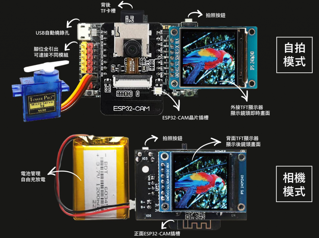
2023/02更新,小霸王EZCAM擴充模組已經上市了,可以直接免接線使用TFT螢幕,並提供範例程式,請參考:https://www.nmking.io/index.php/2023/03/12/982/
以往使用ESP32CAM都要透過網路傳輸影像,不然就是拍照放在SD卡,之前有教過拍照然後送到Azure做臉部辨識,但是發現學生總是把照片拍了上下顛倒,或者歪歪扭扭,導致辨識不出來,抱怨說,沒辦法先預覽對準,所以不知道拍到什麼。
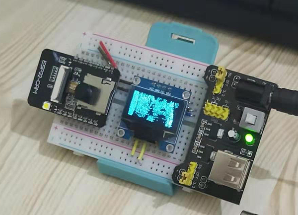
網路找了一些範例,主要有兩種,一種是I2C的OLED,不過畫質很差,主要OLED只有兩色,所以顯示效果類似黑白照片,例如:ESP32-CAM获取的图像显示在OLED上面
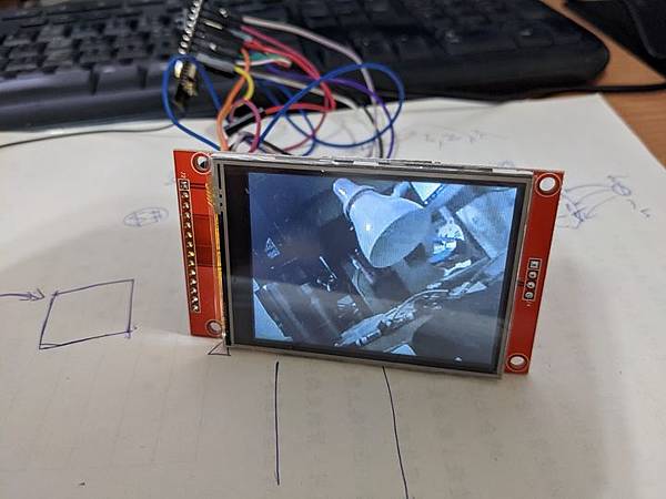
另外一種就是SPI TFT,畫面較為流暢,還可以觸控(本文沒有用到),畫面就漂亮多了,本文主要參考這篇:ESP32-CAM: 連接ILI9341液晶螢幕,然後做了小小修改
ESP32CAM+USBTTL(或ESP32CAM CH340)
SPI TFT,型號:TJCTM24028-SPI
杜邦線若干
環境設定請參考這篇:ESP32-CAM (arduino)影像伺服器及臉部辨識教學原始檔Video Stream Server,也請先使用範例程式進行測試。
請依照下表完成接線
| TFT | ESP32CAM |
|---|---|
| SDO(MISO) | 12 |
| LED | 3.3V (VCC) |
| SCK | 14 |
| SDI(MOSI) | 13 |
| D/C | 2 |
| RESET | 16 |
| CS | 15 |
| GND | GND |
| VCC | 3.3V (VCC) |
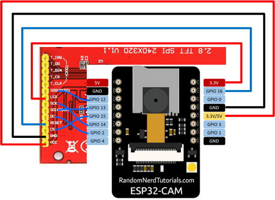
原本的文章RESET是接在4,導致閃光亮到眼睛睜不開,所以這裡改用16
一共有兩個程式庫要安裝
TFT程式庫:關鍵字輸入”TFT_eSPI”,然後找到作者是”Bodmer”的這個,點安裝。

TJpg_Decoder解碼器:關鍵字輸入”TJpg_Decoder”,然後找到作者是”Bodmer”的這個,點安裝。

安裝完畢之後,需要修改一下程式庫內的User_Setup.h,主要是因為程式庫內設計是給ESP32而不是ESP32CAM用的,所以要補上一些腳位定義
避免麻煩大家補錯,可以直接下載這個檔案:https://bit.ly/3oRCcyj
並覆蓋掉程式庫內的User_Setup.h,User_Setup.h一般是在「C:\Users\你的帳號\Documents\Arduino\libraries\TFT_eSPI」
程式碼原始檔如下:
#include "esp_camera.h"
#include "SPI.h"
#include <TFT_eSPI.h>              // Hardware-specific library
#include <TJpg_Decoder.h>

#define PWDN_GPIO_NUM     32
#define RESET_GPIO_NUM    -1
#define XCLK_GPIO_NUM      0
#define SIOD_GPIO_NUM     26
#define SIOC_GPIO_NUM     27
#define Y9_GPIO_NUM       35
#define Y8_GPIO_NUM       34
#define Y7_GPIO_NUM       39
#define Y6_GPIO_NUM       36
#define Y5_GPIO_NUM       21
#define Y4_GPIO_NUM       19
#define Y3_GPIO_NUM       18
#define Y2_GPIO_NUM        5
#define VSYNC_GPIO_NUM    25
#define HREF_GPIO_NUM     23
#define PCLK_GPIO_NUM     22

uint16_t  dmaBuffer1[16 * 16]; // Toggle buffer for 16*16 MCU block, 512bytes
uint16_t  dmaBuffer2[16 * 16]; // Toggle buffer for 16*16 MCU block, 512bytes
uint16_t* dmaBufferPtr = dmaBuffer1;
bool dmaBufferSel = 0;

TFT_eSPI tft = TFT_eSPI();         // Invoke custom library

// This next function will be called during decoding of the jpeg file to render each
// 16x16 or 8x8 image tile (Minimum Coding Unit) to the TFT.
bool tft_output(int16_t x, int16_t y, uint16_t w, uint16_t h, uint16_t* bitmap)
{
  // Stop further decoding as image is running off bottom of screen
  if ( y >= tft.height() ) return 0;
  if (dmaBufferSel) dmaBufferPtr = dmaBuffer2;
  else dmaBufferPtr = dmaBuffer1;
  dmaBufferSel = !dmaBufferSel; // Toggle buffer selection
  //  pushImageDMA() will clip the image block at screen boundaries before initiating DMA
  tft.pushImageDMA(x, y, w, h, bitmap, dmaBufferPtr); // Initiate DMA - blocking only if last DMA is not complete
  // The DMA transfer of image block to the TFT is now in progress...

  // Return 1 to decode next block.
  return 1;
}


void setup() {
  Serial.begin(115200);
  Serial.setDebugOutput(true);
  Serial.println();
  camera_config_t config;
  config.ledc_channel = LEDC_CHANNEL_0;
  config.ledc_timer = LEDC_TIMER_0;
  config.pin_d0 = Y2_GPIO_NUM;
  config.pin_d1 = Y3_GPIO_NUM;
  config.pin_d2 = Y4_GPIO_NUM;
  config.pin_d3 = Y5_GPIO_NUM;
  config.pin_d4 = Y6_GPIO_NUM;
  config.pin_d5 = Y7_GPIO_NUM;
  config.pin_d6 = Y8_GPIO_NUM;
  config.pin_d7 = Y9_GPIO_NUM;
  config.pin_xclk = XCLK_GPIO_NUM;
  config.pin_pclk = PCLK_GPIO_NUM;
  config.pin_vsync = VSYNC_GPIO_NUM;
  config.pin_href = HREF_GPIO_NUM;
  config.pin_sscb_sda = SIOD_GPIO_NUM;
  config.pin_sscb_scl = SIOC_GPIO_NUM;
  config.pin_pwdn = PWDN_GPIO_NUM;
  config.pin_reset = RESET_GPIO_NUM;
  config.xclk_freq_hz = 10000000;
  config.pixel_format = PIXFORMAT_JPEG;
  config.frame_size = FRAMESIZE_QVGA; //FRAMESIZE_QVGA 320x240
  config.jpeg_quality = 10; //< Quality of JPEG output. 0-63 lower means higher quality
  config.fb_count = 2; //Number of frame buffers to be allocated. If more than one, then each frame will be acquired (double speed)

  // camera init
  esp_err_t err = esp_camera_init(&config);
  if (err != ESP_OK) {
    Serial.printf("Camera init failed with error 0x%x", err);
    return;
  }

  sensor_t * s = esp_camera_sensor_get();
  s->set_contrast(s, 2);       // -2 to 2
  s->set_saturation(s, 1);     // -2 to 2

  // Initialise the TFT
  tft.begin();
  tft.setTextColor(TFT_WHITE, TFT_BLACK);
  tft.fillScreen(TFT_BLACK);
  tft.setTextColor(TFT_ORANGE, TFT_BLACK);
  tft.setRotation(3);//1:landscape 3:inv. landscape


  tft.initDMA(); // To use SPI DMA you must call initDMA() to setup the DMA engine
  // The jpeg image can be scaled down by a factor of 1, 2, 4, or 8
  TJpgDec.setJpgScale(1);
  // The colour byte order can be swapped by the decoder
  // using TJpgDec.setSwapBytes(true); or by the TFT_eSPI library:
  tft.setSwapBytes(true);
  // The decoder must be given the exact name of the rendering function above
  TJpgDec.setCallback(tft_output);
}

void loop() {
  camera_fb_t *fb = NULL;
  esp_err_t res = ESP_OK;
  fb = esp_camera_fb_get();
  if (!fb) {
    Serial.println("Camera capture failed");
    esp_camera_fb_return(fb);
    return;
  }

  size_t fb_len = 0;
  if (fb->format != PIXFORMAT_JPEG) {
    Serial.println("Non-JPEG data not implemented");
    return;
  }
  // Must use startWrite first so TFT chip select stays low during DMA and SPI channel settings remain configured
  tft.startWrite();
  // Draw the image, top left at 0,0 - DMA request is handled in the call-back tft_output() in this sketch
  //TJpgDec.drawJpg(0, 0, panda, sizeof(panda));
  TJpgDec.drawJpg(0, 0,  fb->buf, fb->len);
  // Must use endWrite to release the TFT chip select and release the SPI channel
  tft.endWrite();
  esp_camera_fb_return(fb);
}
如果畫面一片空白,RST幾次就正常了